

The hardware has been fully assembled on a single half-sized breadboard. The hardware consists of the following components:
- ESP8266 NodeMCU v1.0
- Bipolar Stepper Motor
- A4988 Stepper Motor Driver
- rcwl-0516 Microwave radar sensor
- RGB LED strips
- Step-down DC-DC power module
- Microswitches
- resistors (330 Ohm, 1 kOhm) and capacitor (100 uF)
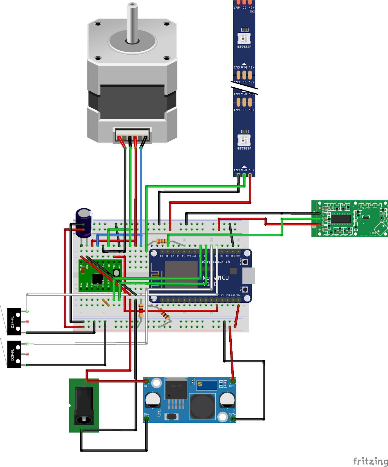
After extensive testing of all the components, the electronics was ready to be reduced into a smaller workspace to better fit inside our product. We managed to fit it all on a half-sized breadboard. The electronics runs through a single 12 V DC-power supply making it easy plug and use as no other cables are needed to power on the device. The 12 V power supply is connected directly to the stepper motor and it’s driver and stepped down to 5 V to power the NodeMCU, sensor and LED strips. Our product does not require any batteries, just the power supply plugged in to the wall.
Using a single power supply to supply the whole system deemed quite the challenge as initially we thought of using a simple voltage divider using two resistors. However due to the internal impedance of the NodeMCU, the resistors of the voltage divider did not provide enough voltage for the NodeMCU making it a suboptimal solution for our system. We therefore decided to use a step-down DC-DC power module to regulate the 12 V down to 5 V. This makes it possible for our system to run with only the 12 V power supply and provide enough voltage for the NodeMCU without frying the MCU with 12 V.
The microswitches are used to make sure the stepper motor does not exceed the rotation limit in such a way that it would damage the product. We therefore have 2 microswitches for whenever the product has fully opened, and whenever it has fully closed.
The breadboard is fully utilized, having space for all of our components, with some of our components floating freely from the board. Components such as the Stepper Motor, RGB LED strips, Sensor and DC-jack as well as step down power module floats freely as they need to be at a desired location inside our product. This way we can freely move the components wherever we want to best suit our product.
PCB-design
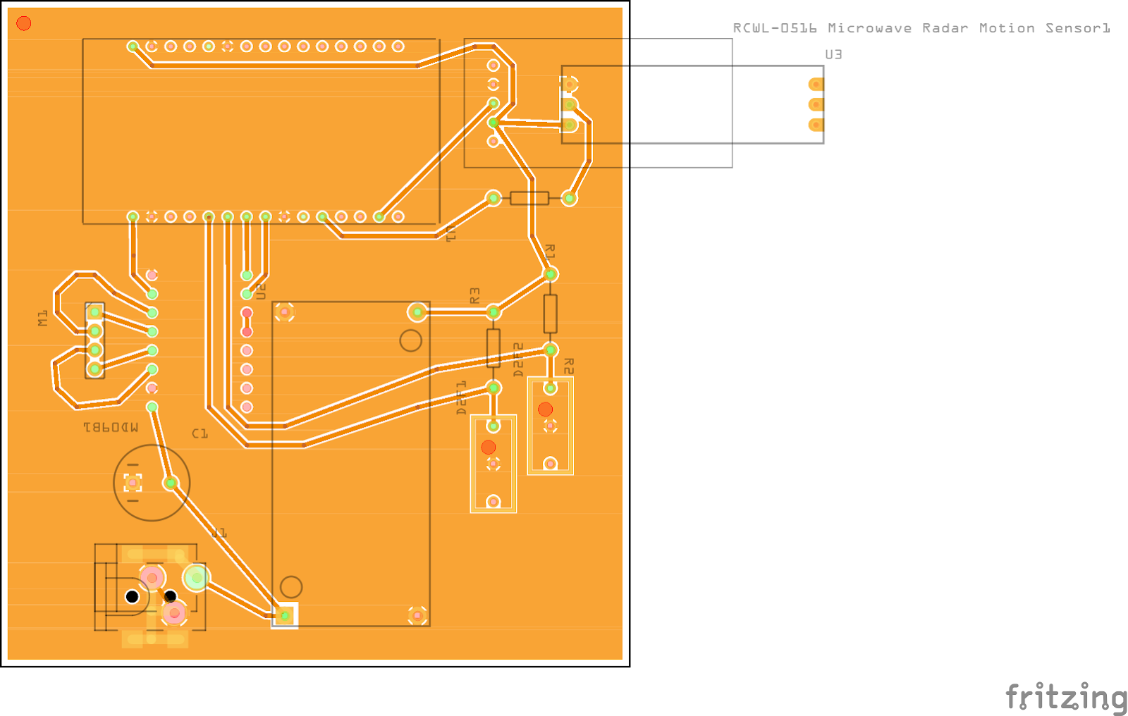
For our product we’d want to assembly our electronics onto a PCB to lessen the wirings and use of jumper cables. To achieve this, we’ve made a PCB-design of our fritzing model of the electronics. the PCB contains all the components from our breadboard setup. We’ve used ground filling for the ground connections to lessen wiring on the PCB and easen the design. The dimensions of the PCB is about 8.5x8.5 cm in size, making it a little larger than our half sized breadboard. At the top right of the PCB some components are pointing out, this is the sensor and LED strip. Because they are only connected at one point of the component and needs to hang freely in wires to place wherever we want in our product, the size of the PCB can be reduced. For the sake of a product the PCB would be a better alternative in the long term for users and stability of our product as with a breadboard, the wirings and components could fall out during transportation or users being rough to the product.
As the facilities of DTU has not yet been fully opened it has not been possible to manufacture the PCB and test it out, the design however remains a task for the next steps of our product.